In This Topic
Overview
The layered graph layout is represented by the NLayeredGraphLayout class. The layered graph layout algorithm aims to highlight the main direction or flow within a directed graph. Cyclic dependencies of nodes are automatically detected and resolved and nodes are placed in hierarchically arranged layers. Additionally, the ordering of the nodes within each layer is chosen in such a way that the number of edge crossings is small. This layout algorithm is very appropriate for hierarchically organized diagrams, organization charts, etc.
The algorithm maintains the following aesthetic criteria (given by their priority in descending order):
- Minimum number of levels
- Minimum number of edge crossings (a level by level sweep optimization is used)
- Minimum number of bends
Following is a brief description of the algorithm.
Algorithm
The input of the layered graph layout algorithm must be a directed acyclic graph (DAG), so if the graph contains cycles a preliminary step that removes them is performed. When we ensure that the input graph is a DAG we may perform the first phase of the algorithm - the Layer Distribution. It distributes the vertices of the graph to layers by using the Longest Path Layering algorithm. All vertices without predecessors are put at level 1 and the other vertices are distributed to the next level / levels in such a way that the following statements are true:
- The final graph must occupy as small area as possible
- The layers must be regular. This can be achieved easily by adding dummy vertices for each edge (u, v) with length more than 1 layer
- The number of added dummy vertices must be minimal
When the vertices are distributed to layers we perform a crossing reduction step which rearranges the vertices on each layer in such way that the number of edge crossings is minimized. Finally we calculate the coordinates of the vertices and edges of the drawing.
Settings
The result of the layout and the aesthetic criteria for the final drawing can be controlled through the following properties:
-
Direction – determines how the drawing is oriented in the 2D drawing space. By default it is oriented from Top to Bottom. Other possible orientations are: from Bottom to Top, from Left to Right and from Right to Left. By default set to TopToBottom.
-
NodeRank - specifies the node ranking policy used by the layout. It can be:
- TopMost - all nodes without incoming edges are assigned to the topmost layer.
- Optimal - similar to the topmost, but after the initial assignment all nodes fall downwards as much as possible. This is the default value.
- Gravity - layer distribution is done in such a way that the total length of all edges (connectors) is minimized.
The image below demonstrates the effect of the different node rank settings on a drawing. Look at the positions of shape 1 and shape 2 for the different NodeRank modes.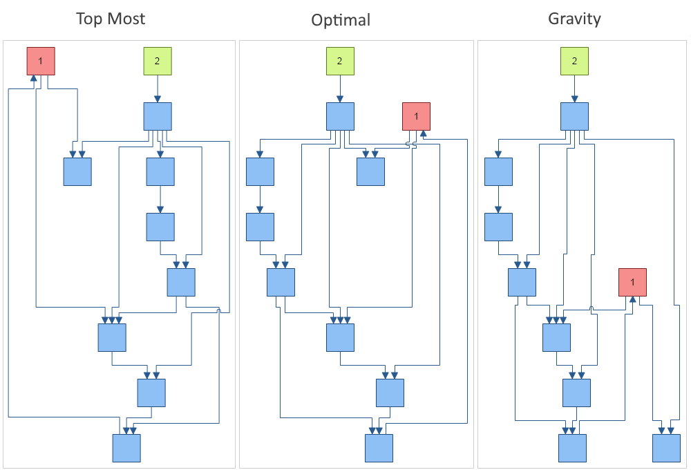
-
LayerSpacing and VertexSpacing – determine the spacing between the layers and the vertices. By default both are set to 40 DIPs (device independent pixels).
-
EdgeRouting – determines whether to use polyline or orthogonal edge routing. The following images illustrate the two possible edge routing modes. By default set to Orthogonal.
|
Layered graph layout with polyline edge routing
|

Layered graph layout with orthogonal edge routing
|
-
PlugSpacing – determines the spacing between the plugs of a node. You can set a fixed amount of spacing or a proportional spacing, which means that the plugs are distributed along the whole side of the node.
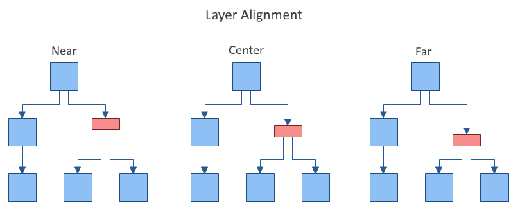
- LayerAlignment – specifies how the vertices are aligned relatively to the layer to which they belong. The possible values are Near, Center and Far. For example: if the direction is TopToBottom, then Near means that the vertices are aligned to the top of the layer, Center – to the center of the layer and Far – to the Bottom of the layer. By default set to Center. The following images illustrate the Near and Far alignment options in a TopToBottom layout direction:
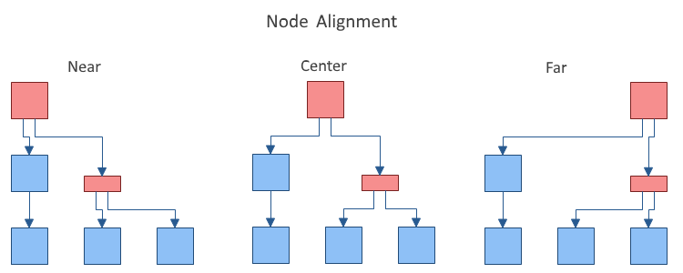
- NodeAlignment - controls the alignment of the vertices relatively to the layer breadth dimension. By default set to Center.
- BusMargin - gets or sets the top and bottom margin (left and right margin for LeftToRight and RightToLeft layouts) to apply to the connector busses lane defined by LayerSpacing in order to determine the size of the area for inter-layer connectors. Should be less than or equal to half of the LayerSpacing. If set to a larger value, LayerSpacing / 2 is used. By default set to 0, which means that connector busses will occupy the whole space between layers.
- SelfLoopSpacingFactor - determines the self-loop spacing factor. It spaces the self-loops as a ratio of the body height.
- CrossingReductionForgivnessNumber - defines the number of times without a reduction to the number of edge crossings after which the crossing reduction algorithm should stop traversing the graph. Lower values lead to better performance but the number of edge crossings might increase. By default set to 20.
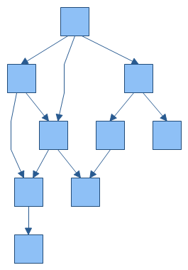
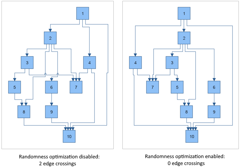
- RandomnessOptimization - gets or sets whether to apply randomness optimization to the layout, which makes the layout not-deterministic (i.e. different runs of the layout result in different output graphs), but almost always results in better positioning of the vertices and less edge crossings. By default set to true. The following image demonstrates the effect of randomness optimization applied to a sample input graph with 10 vertices and 15 edges:
- StraightenLines - if turned on an additional step is performed that tries to straighten the lines as much as possible in the case of orthogonal edge routing. By default set to false.
- UseSingleBus - if true and the EdgeRouting is orthogonal, all edges will be placed on a single bus between each pair of layers. By default set to false.
- Compact - determines whether the layout should try to minimize the width (for TopToBotttom and BottomToTop layouts) or height (for LeftToRight and RightToLeft layouts) of the drawing. By default set to true.
You can set the index of a given node in its layer explicitly using the IndexInLayer property from the LayoutData collection of the node. By default the index is set to -1 which means that the layout will automatically calculate it. If you set a value greater than or equal to 0 the node will be placed at that index. If the index is greater than the total number of nodes in the layer, it will be set equal to the number of vertices - 1.
Self-loops and duplicate edges
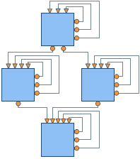
The Layered Graph Layout also handles self-loops and duplicate edges in graphs. The size of the self-loops between 2 layers is determined by the available layer spacing, and the size of the self-loops in the layer is determined by the height of the body multiplied by the SelfLoopSpacingFactor property.
See Also