The barycenter layout is represented by the NBarycenterLayout class. It is a force directed layout, which tries to place all vertices in center of their mass - that is place the vertices in their barycenter. To fulfill this requirement the barycenter layout uses an instance of the NBarycenterForce class, which is accessible by the BarycenterForce property of the NBarycenterLayout class.
Placing all vertices in a single point however is obviously not a good graph drawing, that is why the input set of vertices is split into two distinct sets - fixed and free vertices. As discusses in the Force Directed Layouts topic, the free and fixed vertices placement is controlled by the NFixedVertexPlacement and NFreeVertexPlacement classes, instances of which are accessible from the FixedVertexPlacement and FreeVertexPlacement properties.
In the case of the barycenter layout however, there is an additional constraint, which specifies that there must be 3 or more fixed vertices. This is specified by the MinFixedVerticesCount property. If the input graph does not have than many fixed vertices the barycenter layout will automatically fulfill this requirement. This is done by fixing the vertices with the smallest degree (e.g. count of adjacent edges).
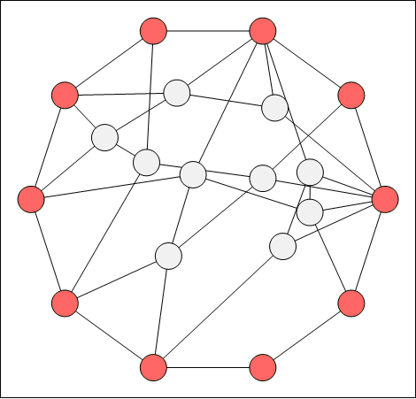
The following image illustrates the result of the barycenter layout:

Figure 1. Barycenter layout - the fixed vertices are shaded in red.
Most of the barycenter layout tuning considerations are related to the placement of the fixed vertices. In practice the fixed vertices are always placed at the corners of a convex polygon (a polygon is convex, if it contains all the line segments connecting any pair of its points).
The positions of the fixed vertices in figure 1 are on the rim of a circle, which is a convex polygon.
You can manually perform this task or ask the layout to perform it for you. This is achieved by the following modes of the NFixedVertexPlacement class:
- Original - the layout does not change the location of the fixed vertices. The user must place the fixed vertices prior to the layout.
- PredefinedEllipseRim - in this mode the fixed vertices are placed on the rim of an ellipse the bounds of which are specified by the PredefinedEllipseBounds property.
- AutomaticEllipseRim - in this mode an automatic ellipse is generated which is large enough not to allow fixed vertex overlapping.
The following code example demonstrates how to instruct the layout to place the vertices on a predefined ellipse rim:
| C# |
Copy Code
|
// fixed vertices are placed on the rim of the specified ellipse
barycenterLayout.FixedVertexPlacement.Mode = FixedVertexPlacementMode.PredefinedEllipseRim;
barycenterLayout.FixedVertexPlacement.PredefinedEllipseBounds = new NRectangleF(0, 0, 700, 500);
|
| Visual Basic |
Copy Code
|
' fixed vertices are placed on the rim of the specified ellipse
barycenterLayout.FixedVertexPlacement.Mode = FixedVertexPlacementMode.PredefinedEllipseRim
barycenterLayout.FixedVertexPlacement.PredefinedEllipseBounds = New NRectangleF(0, 0, 700, 500)
|
Note: When using a predefined or automatic ellipse rim modes the order in which vertices are placed on the ellipse rim is the order in which they occur in the input graph
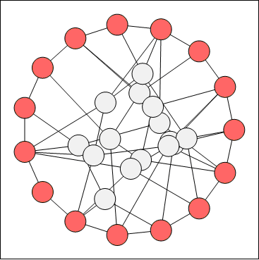
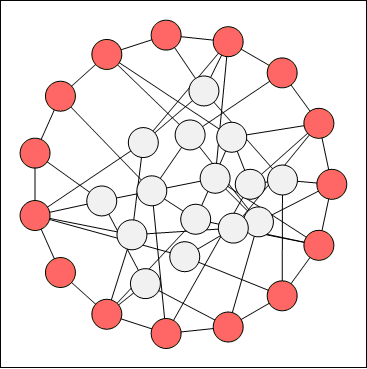
Often the barycenter layout produces many vertex overlaps, especially in high vertex degree cases. In cases like these you may consider enabling the bounce back force:
| C# |
Copy Code
|
barycenterLayout.BounceBackForce.Enabled = true;
|
| Visual Basic |
Copy Code
|
barycenterLayout.BounceBackForce.Enabled = True
|
The following figures show the effect of this force:

figure 2. Barycenter layout without bounce back force

figure 3. Barycenter layout with bounce back force
In general the barycenter layout quickly reaches equilibrium. The best speed performance however is observed when the free vertices are placed in the fixed vertices barycenter:
| C# |
Copy Code
|
barycenterLayout.FreeVertexPlacement.Mode = FreeVertexPlacementMode.FixedBarycenter;
|
| Visual Basic |
Copy Code
|
barycenterLayout.FreeVertexPlacement.Mode = FreeVertexPlacementMode.FixedBarycenter
|
